Opening the book…
A turbofan engine is created by extending a core gas generator with additional low-pressure turbine stages. These stages extract thermal energy from the high-energy exhaust stream to provide mechanical shaft power to a forward fan.
From a thermodynamic standpoint, a fan behaves identically to a low-pressure compressor stage. It is characterized primarily by its total pressure ratio (\(π_f\equiv p_{t13}/p_{t2}\)), total temperature ratio (\(τ_f\equiv T_{t13}/T_{t2}\)), and adiabatic fan efficiency (\(η_f\)).
The adiabatic fan efficiency (\(η_f\)) represents the ratio of ideal (isentropic) enthalpy rise to actual total enthalpy rise across the fan stage:
\[η_f\equiv \dfrac{h_{t13s}-h_{t2}}{h_{t13}-h_{t2}}=\dfrac{Δh_{t,\mathrm{isentropic}}}{Δh_{t,\mathrm{actual}}}=\dfrac{\mathrm{Ideal}~\mathrm{Power}}{\mathrm{Actual}~\mathrm{Power}} \nonumber \]
Dividing the numerator and denominator by \(h_{t2}=c_pT_{t2}\) expresses efficiency in terms of temperature and pressure ratios:
\[η_f=\dfrac{\dfrac{T_{t13s}}{T_{t2}}-1}{\dfrac{T_{t13}}{T_{t2}}-1}=\dfrac{π^{\dfrac{k-1}{k}}_f-1}{τ_f-1} \nonumber \]
Rearranging gives the explicit relations mapping fan temperature rise (\(τ_f\)) and pressure rise (\(π_f\)):
\[τ_f=1+\dfrac{1}{η_f}\left(π^{\dfrac{k-1}{k}}_f-1\right) \nonumber \]
\[π_f={\left[1+η_f\left(τ_f-1\right)\right]}^{\dfrac{k}{k-1}} \nonumber \]
In a turbofan engine, the power extracted by the turbine system must drive both the core high-pressure compressor and the low-pressure bypass fan:
\[\text{Turbine Power Delivered} =\text{Compressor Power Required} + \text{Fan Power Required} \nonumber \]
Accounting for mechanical shaft transmission efficiency (\(η_m\)), primary combustor fuel addition (\(f\equiv {\dot{m}}_f/{\dot{m}}_0\)), and fan bypass ratio (\(α\equiv {\dot{m}}_{\mathrm{fan}}/{\dot{m}}_0\)), the energy balance equation is written as:
\[η_m{\dot{m}}_0\left(1+f\right)\left(h_{t4}-h_{t5}\right)={\dot{m}}_0\left(h_{t3}-h_{t2}\right)+α{\dot{m}}_0\left(h_{t13}-h_{t2}\right) \nonumber \]
Dividing through by the primary air mass flow rate (\({\dot{m}}_0\)) simplifies the expression to specific work terms:
\[η_m\left(1+f\right)c_p\left(T_{t4}-T_{t5}\right)=c_p\left(T_{t3}-T_{t2}\right)+αc_p\left(T_{t13}-T_{t2}\right) \nonumber \]
Dividing the turbofan shaft power balance by core mass flow rate (\({\dot{m}}_0\)) and non-dimensionalizing by flight static enthalpy (\(h_0=c_pT_0\)) yields:
\[η_m\left(1+f\right)\dfrac{h_{t4}}{h_0}\left(1-τ_t\right)=\dfrac{h_{t2}}{h_0}\left[\left(τ_c-1\right)+α\left(τ_f-1\right)\right] \nonumber \]
Substituting the burner temperature parameter (\(τ_λ\equiv h_{t4}/h_0=T_{t4}/T_0\)), ram temperature ratio (\(τ_r\equiv h_{t2}/h_0=T_{t2}/T_0\)), compressor temperature ratio (\(τ_c\)), and fan temperature ratio (\(τ_f\)) allows the turbine temperature ratio (\(τ_t\equiv T_{t5}/T_{t4}\)) to be isolated:
\[τ_t=1-\dfrac{τ_r\left[\left(τ_c-1\right)+α\left(τ_f-1\right)\right]}{η_m\left(1+f\right)τ_λ} \nonumber \]
The primary burner fuel-to-air ratio (\(f\equiv {\dot{m}}_f/{\dot{m}}_0\)) is determined strictly by an energy balance across the main combustion chamber, making it independent of bypass ratio (\(α\)):
\[f=\dfrac{τ_λ-τ_rτ_c}{\dfrac{Q_Rη_b}{h_0}-τ_λ} \nonumber \]
where \(Q_R\) is the lower heating value of the fuel and \(η_b\) is the burner efficiency.
Analyzing the turbine expansion temperature ratio (\(τ_t\)) reveals its strong dependency on both the fan bypass ratio (\(α\)) and the compressor pressure ratio (\(π_c\)), as the total shaft power required for air compression is drawn directly from the turbine system.
To evaluate physical work limits, \(τ_t\) can be decomposed into two distinct loading components:
\[τ_t=1-\dfrac{τ_r\left(τ_c-1\right)}{η_m\left(1+f\right)τ_λ}-\dfrac{τ_rα\left(τ_f-1\right)}{η_m\left(1+f\right)τ_λ}=1-A-B \nonumber \]
Nondimensionalizing the turbofan specific thrust is accomplished by dividing the specific thrust expression (\(F_n/{\dot{m}}_0\)) by the ambient speed of sound (\(a_0=\sqrt{γRT_0}\)):
\[\dfrac{F_n}
Callstack:
    at (Bookshelves/Aerospace_Engineering/Aircraft_Engine:_Design_and_Analysis/04:_Aircraft_Engine-_Gas_Turbine_Engine/4.05:_Turbofan_Engine), /content/body/p[27]/span, line 1, column 1
Applying the general definition of Thrust Specific Fuel Consumption (\(\mathrm{TSFC}\)) to a turbofan cycle, the fuel mass flow rate (\({\dot{m}}_f\)) is scaled against the net uninstalled thrust (\(F_n\)):
\[\mathrm{TSFC}\equiv \dfrac{{\dot{m}}_f}{F_n}=\dfrac{f}{F_n/{\dot{m}}_0} \nonumber \]
where \(f\equiv {\dot{m}}_f/{\dot{m}}_0\) is the core fuel-to-air ratio.
Alternatively, expressing both fuel ratio and specific thrust on a total engine airflow basis (\({\dot{m}}_{\mathrm{total}}={\dot{m}}_0+{\dot{m}}_{\mathrm{fan}}=\left(1+α\right){\dot{m}}_0\)) yields the equivalent form:
\[\mathrm{TSFC}=\dfrac{\dfrac{f}{1+α}}{\dfrac{F_n}{\left(1+α\right){\dot{m}}_0}} \nonumber \]
For an ideal turbofan engine, the cycle thermal efficiency (\(η_{\mathrm{th}}\)) is identical to that of an ideal turbojet operating at the same overall pressure ratio (\(π_c\)), as the fan work transfer is entirely reversible:
\[η_{\mathrm{th}}=1-\dfrac{1}{τ_rτ_c}=1-\dfrac{1}{\left(1+\dfrac{k-1}{2}{Ma}^2_0\right)π^{\dfrac{k-1}{k}}_c} \nonumber \]
For a real (non-ideal) turbofan engine, thermal efficiency is derived directly from the ratio of net kinetic energy generation rate (\(Δ\dot{\mathrm{K}}\mathrm{E}\)) to the total thermal power supplied by the fuel (\({\dot{m}}_fQ_R\)):
\[η_{\mathrm{th}}\equiv \dfrac{Δ\dot{\mathrm{K}}\mathrm{E}}
Callstack:
    at (Bookshelves/Aerospace_Engineering/Aircraft_Engine:_Design_and_Analysis/04:_Aircraft_Engine-_Gas_Turbine_Engine/4.05:_Turbofan_Engine), /content/body/p[36]/span, line 1, column 1
Dividing the numerator and denominator by \({\dot{m}}_0\) expresses efficiency in terms of core and bypass velocity contributions:
\[η_{\mathrm{th}}=\dfrac{αV^2_{19}+\left(1+f\right)V^2_9-\left(1+α\right)V^2_0}{2fQ_R} \nonumber \]
Decomposing the kinetic energy output into core and bypass components yields:
\[η_{\mathrm{th}}=\dfrac{\left(1+f\right)V^2_9-V^2_0}{2fQ_R}+α\left[\dfrac{V^2_{19}-V^2_0}{2fQ_R}\right] \nonumber \]
where: \(V_9\) : Core exhaust exit velocity, \(V_{19}\) : Bypass nozzle exit velocity, \(V_0\) : Flight inlet velocity, \(f=\dfrac{{\dot{m}}_f}{{\dot{m}}_0}\) : Core fuel-to-air ratio.
The propulsive efficiency (\(η_p\)) of a turbofan engine is a strong function of the bypass ratio (\(α\)). It measures how effectively the net kinetic energy generated across both the core and bypass streams is converted into propulsive thrust power:
\[η_p\equiv \dfrac{F_nV_0}{Δ\dot{\mathrm{K}}\mathrm{E}}=\dfrac{\left[\left(1+f\right)V_9+αV_{19}-\left(1+α\right)V_0+\left(p_9-p_0\right)A_9+\left(p_{19}-p_0\right)A_{19}\right]V_0}{\left(1+f\right)\dfrac{V^2_{9,\mathrm{eff}}}{2}+α\dfrac{V^2_{19,\mathrm{eff}}}{2}-\left(1+α\right)\dfrac{V^2_0}{2}} \nonumber \]
Assuming both the core nozzle (\(p_9=p_0\)) and bypass nozzle (\(p_{19}=p_0\)) are perfectly expanded, and neglecting the small core fuel contribution (\(f\ll 1\)), the propulsive efficiency simplifies to:
\[η_p\approx \dfrac{2V_0\left[V_9+αV_{19}-\left(1+α\right)V_0\right]}{V^2_9+αV^2_{19}-\left(1+α\right)V^2_0} \nonumber \]
4.4.1 Mixed exhaust turbofan with an after burner
A mixed exhaust turbofan is an engine configuration where the bypass duct extends all the way to the rear. The cold bypass air and hot core gases combine in an internal forced mixer section (typically featuring a lobed nozzle) before discharging together through a single exhaust nozzle. Figure 9 shows afterburner in mixed exhaust turbofan.
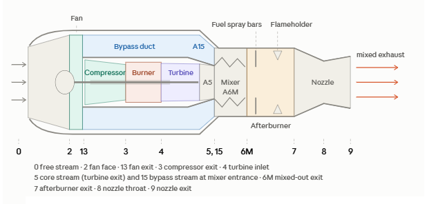
To analyze a constant-area mixer, we apply the fundamental conservation laws of mass, momentum, and energy alongside mixture gas laws to determine the mixed-out properties at the exit. Applying the conservation of energy to an insulated mixer yield:
\[{\dot{m}}_5h_{t5}+{\dot{m}}_{15}h_{t15}={\dot{m}}_{6M}h_{t6M} \nonumber \]
Given known inlet conditions, the only unknown in Equation 4.144 is the mixed-out total enthalpy, \(h_{t6M}\):
\[h_{t6M}=\dfrac{\left(1+f\right)h_{t5}+αh_{t15}}{1+α+f} \nonumber \]
Expressing this relationship in terms of non-dimensional engine parameters gives:
\[h_{t6M}=h_0\cdot \dfrac{\left(1+f\right)τ_tτ_λ+ατ_rτ_f}{1+α+f} \nonumber \]
To determine the mixed-out exit pressure \(p_{6M}\), we apply conservation of \(x\) -momentum along the streamwise direction (Figure 4.49). For steady, uniform flow, the momentum rate is expressed as \(\dot{m}V_x\). Applying this to the mixer control volume:
\[{\dot{m}}_{6M}V_{6M}-\left({\dot{m}}_5V_5+{\dot{m}}_{15}V_{15}\right)=\sum{F_x} \nonumber \]
The term \(\sum{F_x}\) represents the net external force acting on the control volume in the \(x\) -direction, comprised of integrated pressure forces and wall shear stresses over the wetted surface:
\[\sum{F_x}=p_5A_5+p_{15}A_{15}-p_{6M}A_{6M}-\int{τ_w} dA_{\mathrm{wetted}} \nonumber \]
where the surface integral represents the internal wall friction drag, \(D_{f,\mathrm{mixer}}\).
Per the Kutta condition, the static pressures at the core and fan duct inlets are equal:
\[p_5=p_{15} \nonumber \]
Additionally, for a constant-area mixer:
\[A_{6M}=A_5+A_{15} \nonumber \]
Combing the above equations yields:
\[\left({\dot{m}}_{6M}V_{6M}+p_{6M}A_{6M}\right)-\left({\dot{m}}_5V_5+p_5A_5\right)-\left({\dot{m}}_{15}V_{15}+p_{15}A_{15}\right)=-D_{f,\mathrm{mixer}} \nonumber \]
Each grouped quantity \(\left(\dot{m}V+pA\right)\) represents the flow impulse, \(I\), at stations \(6M\), \(5\), and \(15\), respectively. Consequently, the exit impulse is reduced relative to the sum of the inlet impulses due to wall friction.
Energy conservation for an insulated mixer is written as:
\[{\dot{m}}_5h_{t5}+{\dot{m}}_{15}h_{t15}={\dot{m}}_{6M}h_{t6M} \nonumber \]
Solving for the mixed-out total enthalpy \(h_{t6M}\) in terms of inlet variables:
\[h_{t6M}=\dfrac{\left(1+f\right)h_{t5}+αh_{t15}}{1+α+f} \nonumber \]
In non-dimensional form, becomes:
\[h_{t6M}=h_0\left[\dfrac{\left(1+f\right)τ_tτ_λ+ατ_rτ_f}{1+α+f}\right] \nonumber \]
To find the exit pressure \(p_{6M}\), we apply \(x\) -momentum conservation along the flow axis. Assuming steady, 1D flow where momentum flux is \(\dot{m}V_x\):
\[{\dot{m}}_{6M}V_{6M}-\left({\dot{m}}_5V_5+{\dot{m}}_{15}V_{15}\right)=\sum{F_x} \nonumber \]
The net axial force \(\sum{F_x}\) accounts for pressure forces and wetted wall shear stress:
\[\sum{F_x}=p_5A_5+p_{15}A_{15}-p_{6M}A_{6M}-D_{f,\mathrm{mixer}} \nonumber \]
where \(D_{f,\mathrm{mixer}}=\int{τ_w} dA_{\mathrm{wetted}}\) is the mixer friction drag.
Assuming equal inlet static pressures (\(p_5=p_{15}\), via the Kutta condition) and a constant cross-sectional area (\(A_{6M}=A_5+A_{15}\)), yields:
\[\left({\dot{m}}_{6M}V_{6M}+p_{6M}A_{6M}\right)-\left({\dot{m}}_5V_5+p_5A_5\right)-\left({\dot{m}}_{15}V_{15}+p_{15}A_{15}\right)=-D_{f,\mathrm{mixer}} \nonumber \]
Recognizing the term \(\left(\dot{m}V+pA\right)\) as the flow impulse function \(I\), If wall friction is neglected, impulse conservation simplifies to:
\[I_{6M}=I_5+I_{15} \nonumber \]
We make this inviscid assumption to obtain a closed-form analytical solution for the exit state, later introducing an empirical correction factor for total pressure friction losses.
Using \(a^2=kp/ρ\), the impulse \(I\) is recast in Mach number form:
The frictionless impulse equation:
\[p_{6M}A_{6M}\left(1+k_{6M}{Ma}^2_{6M}\right)-p_5A_5\left(1+k_5{Ma}^2_5\right)-p_{15}A_{15}\left(1+k_{15}{Ma}^2_{15}\right)=0 \nonumber \]
Nondimensionalizing by \(A_5\) removes geometric scale:
\[p_{6M}\left(1+k_{6M}{Ma}^2_{6M}\right)\left(1+\dfrac{A_{15}}{A_5}\right)=p_5\left[\left(1+k_5{Ma}^2_5\right)+\dfrac{A_{15}}{A_5}\left(1+k_{15}{Ma}^2_{15}\right)\right] \nonumber \]
Determining the two remaining unknowns (\(p_{6M}\) and \(M_{6M}\)) requires the continuity equation, written in terms of static pressure, Mach number, and total temperature:
\[\dot{m}=\dfrac{kpAMa}{\sqrt{kRT_t}}\sqrt{1+\dfrac{k-1}{2}{Ma}^2} \nonumber \]
Applying mass conservation across the mixer yields:
\[\dfrac{p_{6M}{Ma}_{6M}\sqrt{1+\dfrac{k_{6M}-1}{2}{Ma}^2_{6M}}}{\sqrt{k_{6M}R_{6M}T_{t6M}}}\left(1+\dfrac{A_{15}}{A_5}\right)=\dfrac{p_5{Ma}_5\sqrt{1+\dfrac{k_5-1}{2}{Ma}^2_5}}{\sqrt{k_5R_5T_{t5}}}+\dfrac{p_{15}{Ma}_{15}\sqrt{1+\dfrac{k_{15}-1}{2}{Ma}^2_{15}}}{\sqrt{k_{15}R_{15}T_{t15}}}\left(\dfrac{A_{15}}{A_5}\right) \nonumber \]
This page titled 4.4: Turbofan Engine was last modified on Wed, 18 Nov 2026 07:18:33 GMT and is shared under a CC BY 4.0 license and was authored, remixed, and/or curated by Haifa El-Sadi.
The book could not be loaded just now.