Opening the book…
Aircraft Piston (Reciprocating) Engines operate on internal combustion principles, converting the chemical energy of fuel into kinetic energy through the linear movement of pistons, which is then transformed into rotational movement by a crankshaft to drive a propeller.

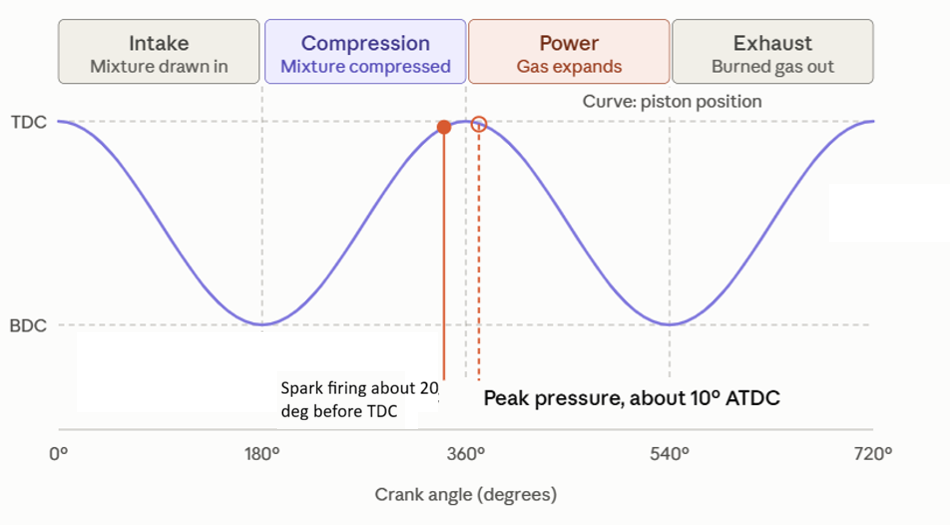
Most aviation piston engines operate on the Four-Stroke (Otto) Cycle as shown in Figure 1, completing four distinct strokes over two full revolutions (\({720}^{\circ }\)) of the crankshaft:
Intake Stroke (\(0^{\circ }-{180}^{\circ }\)):
- The intake valve opens as the piston moves downward from Top Dead Center (TDC) to Bottom Dead Center (BDC).
- A low-pressure area is created, drawing in a vaporized fuel-air mixture from the induction system.
Compression Stroke (\({180}^{\circ }-{360}^{\circ }\)):
- Both valves close. The piston moves upward from BDC to TDC, compressing the fuel-air mixture.
- Just before TDC, twin spark plugs ignite the mixture.
Power (Expansion) Stroke (\({360}^{\circ }-{540}^{\circ }\)):
- The burning air-fuel mixture expands rapidly, driving the piston downward from TDC to BDC.
- This force delivers mechanical work to the crankshaft via the connecting rod.
Exhaust Stroke (\({540}^{\circ }-{720}^{\circ }\)):
- The exhaust valve opens. The piston moves back up from BDC to TDC, forcing burned combustion gases out through the exhaust manifold.
The compression ratio, \(r\), is defined as the ratio of the maximum cylinder volume when the piston is at Bottom Dead Center (BDC) to the minimum cylinder volume when the piston is at Top Dead Center (TDC), expressed mathematically as
\[r=\left(\dfrac{V_d}{V_c}\right)+1, \nonumber\]
where \(V_d\) is the displacement volume per cylinder and \(V_c\) is the clearance combustion chamber volume. For an engine with \(N_c\) cylinders, the total engine displacement \(V_D\) is calculated as
\[V_D=N_c\cdot \left(\dfrac{\pi }{4}{D_B}^2L\right), \nonumber\]
where \(D_B\) represents the cylinder bore diameter and \(L\) denotes the piston stroke length and \(N_c\) is the number of cylinders. In the ideal air-standard Otto cycle, the thermal efficiency \({\eta }_{\mathrm{thermal}}\) depends directly on this compression ratio and the specific heat ratio of air \(k\) through the relationship:
\[{\eta }_{\mathrm{thermal}}=1-\dfrac{1}{r^{k-1}}. \nonumber\]
Although higher compression ratios yield higher thermodynamic efficiency, they are typically limited in aircraft engines to a range of \(7:1\) to \(9:1\) to prevent violent autoignition, also known as knocking or detonation. Furthermore, the work performed during this process can be quantified by the Indicated Mean Effective Pressure (\(\mathrm{IMEP}\)), which represents the theoretical average pressure acting on the piston across the power stroke (\(\mathrm{IMEP}=W_{\mathrm{net, cycle}}/V_d\)). BMEP is the brake mean effective pressure, BMEP = \({\eta }_m IMEP\)
The Indicated Power (\(P_i\)) is the total theoretical work rate generated inside the combustion chambers:
\[P_i=\mathrm{IMEP}\cdot V_D\cdot \left(\dfrac{N}{2\cdot 60}\right) \nonumber \]
where:
- \(N\) = Engine speed in Rotational Speed (\(\mathrm{RPM}\))
- The factor of \(2\) accounts for power stroke occurring once every \(2\) crankshaft revolution.
The Brake Power (\(P_b\)) is the actual usable power delivered at the propeller shaft after overcoming internal friction and accessory losses:
\[P_b={\eta }_m\cdot P_i=\tau \cdot \omega =\dfrac{2\pi \cdot \tau \cdot N}{60} \nonumber \]
where:
- \({\eta }_m\) = Mechanical efficiency (\(\approx 80\%-90\%\))
- \(\tau\) = Shaft torque (\(\mathrm{N}\cdot \mathrm{m}\))
- \(\omega\) = Shaft angular speed (\(\mathrm{rad/s}\))
Engine fuel performance can be evaluated using Brake Specific Fuel Consumption (\(\mathrm{BSFC}\)), which measures how effectively the engine converts fuel mass into usable mechanical work.
\[\mathrm{BSFC}=\dfrac{{\dot{m}}_f}{P_b} \nonumber \]
where:
- \({\dot{m}}_f\) = Fuel mass flow rate, cruise (\(\mathrm{kg/s}\) or \(\mathrm{lb/hr}\))
- \(P_b\) = Brake Power (\(\mathrm{kW}\) or \(\mathrm{hp}\))
Thrust power is the power delivered by the propeller, THP,
\[ THP = \dfrac{(T \mathrm{\times} V \mathrm{\infty})}{550} \nonumber\]
or
\[\mathrm{THP}=P_b\times {\eta }_p \nonumber \]
where: \(T\) is the thrust, Ibf \(V\mathrm{\infty}\) is aircraft speed, ft/s Friction horsepower is the power loss due to friction and supercharger, FP, \(FP = P_{i}\) - P_{b}\)
Modern aircraft piston engines incorporate several key operational features to ensure reliability, performance, and efficiency at high altitudes. Most aviation engines, such as the Lycoming O-360 and Continental IO-550, utilize air-cooled, horizontally opposed configurations to minimize overall system weight and reduce aerodynamic drag compared to liquid-cooling systems. To maximize safety and performance, these engines employ dual ignition systems featuring two independent magnetos that power two spark plugs per cylinder; this design provides critical redundancy while ensuring a more uniform combustion flame front. Finally, to combat the loss of manifold pressure and air density at higher altitudes, many systems incorporate turbochargers that compress ambient intake air, allowing naturally aspirated engines to maintain sea-level power output up to high critical altitudes.
The Otto cycle is a thermodynamic cycle (constant-volume heat addition, spark ignition). A spark-ignition (SI) engine can use either a carburetor (way of mixing fuel and air) or fuel injection.
3.2.1 Otto Cycle Engine: Carburetor
Carburetors govern fuel metering through fluid dynamics and pressure differentials created across a venturi tube. It is used for light aircraft like the Cessna 150/172
A. Air Mass Flow Rate (\({\dot{m}}_a\))
Assuming incompressible flow for low-speed intake air across the venturi throat (Bernoulli’s Principle):
\[P_1+\dfrac{1}{2}{\rho }_aV^2_1=P_2+\dfrac{1}{2}{\rho }_aV^2_2 \nonumber \]
\[\mathrm{\Delta }P=P_1-P_2=\dfrac{1}{2}{\rho }_a\left(V^2_2-V^2_1\right) \nonumber \]
Applying continuity (\({\dot{m}}_a={\rho }_aA_tV_t\)) and incorporating the discharge coefficient \(C_{da}\) to account for fluid friction:
\[{\dot{m}}_a=C_{da}A_t\sqrt{\dfrac{2{\rho }_a\mathrm{\Delta }P}{1-{\left(A_t/A_1\right)}^2}}\approx C_{da}A_t\sqrt{2{\rho }_a\mathrm{\Delta }P} \nonumber \]
- \(P_1,P_2\): Inlet atmospheric pressure and venturi throat pressure (\(\mathrm{Pa}\))
- \(ρ_a\): Density of intake air (\({\mathrm{kg/m}}^3\))
- \(A_1,A_t\): Cross-sectional area of inlet and venturi throat (\({\mathrm{m}}^2\))
- \(C_{da}\): Discharge coefficient of the air throat (\(\sim 0.85--0.95\))
The intake air mass flow rate \({\dot{m}}_a\) using the simplified venturi relation
\[{\dot{m}}_a=C_{da}A_t\sqrt{2ρ_aΔP} \nonumber \]
B. Fuel Mass Flow Rate (\({\dot{m}}_f\))
Fuel is drawn from the float chamber through the main jet orifice. Considering the fuel lip height (\(h\)) above the float level to prevent spillage at rest:
\[{\dot{m}}_f=C_{df}A_f\sqrt{2ρ_f\left(ΔP-ρ_fgh\right)} \nonumber \]
- \(C_{df}\): Discharge coefficient of the fuel jet (\(\sim 0.60--0.75\))
- \(A_f\): Area of the fuel jet metering orifice (\({\mathrm{m}}^2\))
- \(ρ_f\): Density of liquid fuel (\({\mathrm{kg/m}}^3\))
- \(h\): Fuel nozzle lip height above the float bowl fuel level (\(\mathrm{m}\))
- \(g\): Acceleration due to gravity (\(9.81 {\mathrm{m/s}}^2\))
C. Delivered Air-Fuel Ratio (\(AFR\))
\[\mathrm{AFR}=\dfrac{{\dot{m}}_a}{{\dot{m}}_f}=\dfrac{C_{da}A_t}{C_{df}A_f}\sqrt{\dfrac{ρ_a}{ρ_f}\left(\dfrac{ΔP}{ΔP-ρ_fgh}\right)} \nonumber \]
Note: At high airflows (\(ΔP\gg ρ_fgh\)), the pressure drop terms cancel out, leaving the air-fuel ratio governed purely by geometric areas (\(\dfrac{A_t}{A_f}\)) and fluid densities.
3.2.2 Otto Cycle Engine: Fuel Injection Equations
Electronic fuel injection calculates the required fuel mass per stroke using sensor inputs (e.g., MAP sensor, MAF sensor, engine RPM) and actuates solenoid or piezoelectric valves. It comes in two main forms: Port Fuel Injection (PFI), in which fuel is sprayed into the intake port just upstream of the intake valve and mixes with air before entering the cylinder, and Gasoline Direct Injection (GDI), in which fuel is sprayed at high pressure directly into the combustion chamber, allowing finer control of timing and mixture but requiring much higher injection pressures.
A. Air Mass per Cylinder per Cycle (\(m_a\))
Calculated using volumetric efficiency (\(η_v\)) and engine displacement volume (\(V_d\)):
\[m_a=η_v\cdot ρ_{a,\mathrm{manifold}}\cdot \left(\dfrac{V_d}{n_{\mathrm{cyl}}}\right) \nonumber \]
- \(η_v\): Volumetric efficiency of the engine (ratio of actual air mass to theoretical cylinder volume)
- \(V_d\): Total engine displacement volume (\({\mathrm{m}}^3\))
- \(n_{\mathrm{cyl}}\): Number of cylinders
B. Required Fuel Mass per Injection Event (\(m_f\))
\[m_f=\dfrac{m_a}{\mathrm{AFR}_{\mathrm{target}}} \nonumber \]
C. Fuel Injector Flow Rate (\({\dot{m}}_{f,\mathrm{inj}}\))
Modeled via the orifice flow equation across the injector nozzle tip:
\[{\dot{m}}_{f,\mathrm{inj}}=C_dA_{\mathrm{orif}}\sqrt{2ρ_f\left(P_{\mathrm{fuel}}-P_{\mathrm{manifold}}\right)} \nonumber \]
- \(P_{\mathrm{fuel}}-P_{\mathrm{manifold}}\): Differential injection pressure across the nozzle (\(ΔP_{\mathrm{inj}}\))
- For PFI: \(P_{\mathrm{fuel}}-P_{\mathrm{manifold}}\approx 3--6mathrm{bar}\)
- For GDI: \(P_{\mathrm{fuel}}-P_{\mathrm{cylinder}}\approx 150--350+mathrm{bar}\)
D. The duration the injector orifice must be fully open to deliver \(m_f\) is (\(t_{\mathrm{inj}}\)):
\[t_{\mathrm{inj}}=\dfrac{m_f}{\dot{m}_{f,\mathrm{inj}}} \nonumber \]
\({t}_{total}\) = \(t_{\mathrm{inj}}+t_{\mathrm{dead}}\)
- \(t_{\mathrm{dead}}\): Electrical dead time / latency (delay for solenoid coil energization and needle lift, typically \(0.5--1.5 \mathrm{ms}\)) where ms is milliseconds
3.2.3 Ignition system
The battery supplies 12 V through the ignition switch to the coil’s primary winding, and current builds up a magnetic field in the coil. The crank sensor (or the cam in a points system) reports piston position, so the control unit knows when to fire. At the right moment, the interrupter (breaker points in older engines, a transistor or ECU in modern ones) cuts the primary current. The magnetic field collapses, which induces a very high voltage, typically 20-40 kV, in the coil’s secondary winding. The distributor routes that pulse to the correct cylinder, and the spark plug sparks across its gap (Figure 2), igniting the compressed fuel-air mixture shortly before TDC as indicated in Figure 3.

Modern engines with coil-on-plug ignition have no distributor. Each cylinder has its own coil, and the ECU sends the pulses directly. A magneto system, as used in aircraft, combines the source, coil and interrupter in one self-powered unit, so it needs no battery or ignition switch in the power path
This page titled 3.1: Aircraft Piston Engine was last modified on Wed, 18 Nov 2026 15:56:37 GMT and is shared under a CC BY 4.0 license and was authored, remixed, and/or curated by .
The book could not be loaded just now.