Opening the book…
Figure below shows a photodiode amplifier for measuring low levels of light. Best sensitivity and bandwidth are obtained with a trans-impedance amplifier, a current to voltage amplifier, instead of a conventional operational amplifier. The photodiode remains to reverse biased for lowest diode capacitance, hence wider bandwidth, and lower noise. The feedback resistor sets the “gain”, the current to voltage amplification factor. Typical values are 1 to 10 Meg Ω. Higher values yield higher gain. A capacitor of a few pF may be required to compensate for photodiode capacitance and prevents instability at the high gain. The wiring at the summing node must be as compact as possible. This point is sensitive to circuit board contaminants and must be thoroughly cleaned. The most sensitive amplifiers contain the photodiode and amplifier within a hybrid microcircuit package or single die.
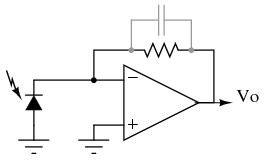
Photodiode amplifier.
This page titled 9.8: Measurement Circuits was last modified on Sat, 20 Mar 2021 03:12:34 GMT and is shared under a GNU Free Documentation License 1.3 license and was authored, remixed, and/or curated by Tony R. Kuphaldt (All About Circuits) via source content that was edited to the style and standards of the LibreTexts platform.
The book could not be loaded just now.