Opening the book…
1. The figure below shows the relationship between azimuth and compass quadrant bearings. In the table you will find strike measurements recorded using both systems. In the blank boxes determine the correct measurement to properly navigate between the two systems.
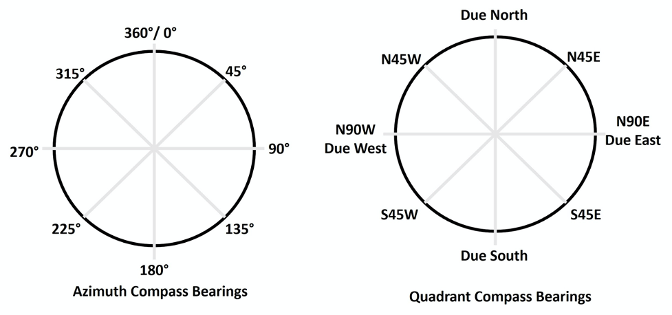
Table 16.4: Table for Question 1, Activity 16A.
| Quadrant | Due North | N20W | S52W | Due East | N88E | |||||
|---|---|---|---|---|---|---|---|---|---|---|
| Azimuth | 110° | 270° | 77° | 305° | 180° |
Attributions
- Figure 16.12: “Navigating Compass Bearings” (CC-BY; Chloe Branciforte, own work)
- Table 16.4: “Navigating the Compass Systems” (CC-BY; Chloe Branciforte, own work)
This page titled 16.2: Activity 16A - Navigating the Azimuth and Quadrant Systems was last modified on Fri, 06 May 2022 23:29:55 GMT and is shared under a not declared license and was authored, remixed, and/or curated by Chloe Branciforte and Emily Haddad (ASCCC Open Educational Resources Initiative) .
The book could not be loaded just now.