Opening the book…
Magnetic flowmeters have been used for the measurement of pipeline flows for many years but only recently have gained economic acceptance in agricultural irrigation. Magnetic flowmeters use the principle of Faraday’s Law where the voltage induced across a conductor that is moving at a right angle through a magnetic field is proportional to the average velocity of the conductor. In this case, water with solutes is the conductor. Inline or tube magnetic flow meters are illustrated in Figures 3.14 and 3.15. Battery operated magnetic flow meters have been developed to increase their applicability in irrigation. Research has shown that the in-line magnetic flow meters require less upstream distance from flow disturbances as compared to other meter types. For example, rather than needing 10 pipe diameters upstream and 1 downstream of straight unobstructed pipe between a flow disturbance and the metering section (as is the case for propeller meters), only 2 are needed upstream and 1 downstream for magnetic flow meters. Depending upon the situation, these shorter required distances can be a significant savings in the costs of retrofitting a piping system to accommodate metering.
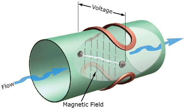
Figure 3.14. In-line magnetic flowmeter. (Modification of diagram provided courtesy of McCrometer Corporation.)
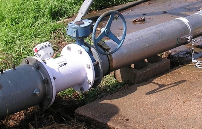
Figure 3.15. Electromagnetic flowmeter installed in the field.
3.3.4: Magnetic Flowmeters is shared under a CC BY-NC-ND 4.0 license and was authored, remixed, and/or curated by LibreTexts.
The book could not be loaded just now.