Opening the book…
In this exercise, we’re going to create response-locked averages rather than stimulus-locked averages. That is, when we create our EEG epochs, the event code for the response will be time zero.
An important feature of BINLISTER is that it does not make a distinction between stimulus events and response events. An event code is an event code, no matter whether it represents a stimulus, a response, an eye movement, a heartbeat, or a sudden change in the FTSE stock index. Any event code can be the time-locking event (time zero). And a bin can be defined by any sequence of event codes.
Open the bin descriptor file named BDF_P3_Response_Locked.txt in the Matlab text editor (by double-clicking it in the Current Folder pane). Here’s what you should see:
bin 1
Rare, Correct
{t<200-1000>11;22;33;44;55}.{201}
bin 2
Frequent, Correct
{t<200-1000>12;13;14;15;21;23;24;25;31;32;34;35;41;42;43;45;51;52;53;54}.{201}
It’s a lot like the original bin descriptor file (BDF_P3.txt). The most important change is that the period symbol in each bin descriptor is to the left of the response event list rather than being to the left of the stimulus event list. The period goes to the left of the time-locking event, so this is how we indicate that the response event code (201) will be the time-locking event. Also, the t<200-1000> part now appears as part of the stimulus event list. The timing is always given relative to the time-locking event, which is now the response, so we need to specify that the stimulus must be 200-1000 ms prior to the response rather than the response being 200-1000 ms after the stimulus.
Start by clicking the Reset button under the lower right corner of the plot region and then clicking Reset ERPLAB Studio in the window that appears. Then load 12_P3_corrected_elist.set (which you created in an earlier exercise) using the EEGsets panel. Then go to the Assign Events to Bins (BINLISTER), load BDF_P3_Response_Locked.txt as the bin descriptor file, and click Run. You can name the new EEGset 12_P3_corrected_elist_resplock.
Now go to the EventList panel and click the View button to look at the updated EventList. If you look at the bin column on the far right, you’ll now see bin numbers on the lines for the response events (event code 201 ), with a 1 if the response is preceded by a target event code (11, 22, 33, 44, or 55) and a 2 if the response is preceded by a nontarget event code. This shows us that the responses will be used as time zero when we epoch and then average the data.
Close the EventList window and then epoch the data using the Extract Bin-Based Epochs panel with the settings shown in Screenshot 6.8. Rather than using the default epoch of -200 to 800 ms, we’re now using an epoch of -600 to 400 ms. This is because much of the activity occurs before rather than after time zero in a response-locked average. Also, rather than using Pre as the baseline correction interval (which would use the period from -600 to 0 ms), we're using a Custom baseline period of -600 -400. This period should be prior to stimulus onset on most trials because most of the RTs are <400 ms. (See this page in the ERPLAB Studio Tutorial to read about a way to “trick” ERPLAB into using the actual prestimulus interval as the baseline in a response-locked average.) Click Apply and name the resulting EEGset 12_P3_corrected_elist_resplock_be.
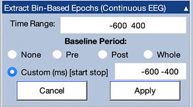
Screenshot 6.8
If you look at the EEG waveforms for the first epoch, you’ll see an event code labeled B2(201) at time zero. The B2 means that this epoch has been assigned to Bin 2, and the 201 indicates that the event code was 201. You’ll also see that the epoch begins 600 ms before this event and ends 400 ms after the event. You can’t see the stimulus event code prior to this response because it was more than 600 ms prior to the response and therefore falls outside the epoch. (You can verify this by looking at the diff column in the EventList.) However, you can see the stimulus event code prior to the response in the second epoch. The stimulus event code isn’t at time zero, and it doesn’t begin with B2 because it wasn’t the time-locking event. Scroll through several pages of epochs to make sure you understand what’s in this file.
Now average the data using the Compute Averaged ERPs panel, just as you did for the stimulus-locked data, but using 12_P3_Response_Locked when you are prompted for the name of the ERPset. You'll see a new window showing the number of trials per bin and a summary of the aSME values. You can close that window and look at the ERP waveforms in the ERP tab.
After you've looked at all the ERP waveforms, select Pz in the Bin & Channel Selection panel to get a close-up view of this channel (see Screenshot 6.9). You can see that the brain activity now begins approximately 200 ms before the time-locking event (the response), because the stimulus is now before time zero. In addition, the P3 peaks shortly after time zero.

Screenshot 6.9
The P3b component is usually tightly time-locked to the participant’s decision about whether the current stimulus belongs to the Rare category or the Frequent category, so P3b latency usually (but not always) varies from trial to trial according to the response time. As a result, it can be informative to look at the P3b waveform in both stimulus- and response-locked averages. For an example from the basic science literature, see Luck & Hillyard (1990) or the condensed description of that study in Luck (2014; especially Figure 8.8 and the surrounding text). For an example with a clinical population, see Luck et al. (2009).
This page titled 6.8: Exercise - Response-Locked Averaging was last modified on Thu, 01 Oct 2026 18:52:56 GMT and is shared under a CC BY-NC 4.0 license and was authored, remixed, and/or curated by Steven J Luck directly on the LibreTexts platform.
The book could not be loaded just now.