Opening the book…
The next step in processing Subject 6’s data is quite simple, and it involves two operations that are performed together in a single step. One of these operations is extracting a fixed-length epoch (time segment) for each event that has been assigned to a bin. If you’re not quite sure what this means, see Figure A1.3 in Appendix 1. As shown in Figure 2.1 in Section 2.2, we will be looking at the data from 200 ms prior to stimulus onset through 800 ms after stimulus onset. Consequently, for each trial we need to extract an epoch that starts 200 ms before the time-locking event code and extends until 800 ms after the event code.
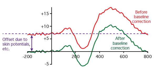
The second operation will be baseline correction, which is a way of dealing with the DC voltage offsets. As shown in Figure 2.3, this exercise uses the average voltage during the prestimulus period as an estimate of the offset, and the baseline correction process shifts the whole waveform upward or downward so that the average voltage during this period becomes zero.
To perform these steps on our example data, make sure that the dataset created during the previous exercise (6_N400_preprocessed_filt_elist_bins) is loaded and selected in the EEGsets panel. Then go to the Extract Bin-Based Epochs panel, enter -200 800 as the Time Range, and select Pre for baseline correction (as in Screenshot 2.12). The time window values tell the routine that you want the epochs to start 200 ms before stimulus onset and extend for 800 ms after stimulus onset, for a total epoch length of 1000 ms. The baseline period parameter tells the routine that you want to use the entire prestimulus interval (-200 to 0 ms) as the baseline period. Once you’ve set these parameters, click Apply. Accept the suggestion for the new EEGset name (6_N400_preprocessed_filt_elist_bins_be). If you’re not going to do the next exercise right away, you should indicate that you want to save the new EEGset to disk.

Screenshot 2.12
Looking at the Epoched EEGset
The epoched EEGset should now be visible in eStudio's plotting region (and should look like Screenshot 2.13). Five epochs are shown per screen by default. You can see an event code at time zero in each epoch, with 200 ms of data prior to time zero and 800 ms of data afterward. Note that the time values on the X axis are now in milliseconds.

Screenshot 2.13
The event code at time zero is now labeled with the bin number, with the event code in parentheses. For example, the event code for the first epoch is labeled B2(121), which means that this epoch was assigned to Bin 2 when you ran BINLISTER, and it had an event code of 121. When we create our averaged ERPs, all the epochs labeled B1 will be averaged together to form Bin 1 (whether the actual event code was 111 or 112), all the epochs labeled B2 will be averaged together to form Bin 2 (whether the actual event code was 121 or 122), etc.
Note that the second epoch contains an event code labeled 201 shortly after the 500 ms mark. This was the response to the target word. We’re not using it as the time-locking point for any bins, so it does not have a bin number. However, the information about the event is still present, so you can see the event code in the plot.
Scroll through the epochs using the +X button at the bottom of the plotting window. Notice that there is usually a response event code following the target words (Bins 3 and 4) but not following the prime words (Bins 1 and 2). Sometimes the response event code is missing; this happens when the response was later than 800 ms and therefore fell outside of the time window of the epochs. You might find it useful to view the EventList (by clicking View in the EventList panel) so you can compare the contents of the EventList to what you’re seeing in the epoched EEG data.
You’ll see a large positive voltage deflection in the frontal channels (especially Fp1 and Fp2) in many of the epochs, accompanied by a negative deflection in the VEOG channel. These voltage deflections were produced by eyeblinks—this participant blinked a lot! Most of the blinks occurred in the epochs for the prime words, not the target words. This is fortunate, because we mainly care about the ERPs elicited by the target words in this experiment.
Don’t make this mistake!
EEGLAB also has a routine for extracting epochs from the continuous EEG (EEGLAB > Tools > Extract epochs), but do not use it!!! The EEGLAB routine knows nothing about bins, so the epochs won’t contain the bin information that you’ll need for the rest of the ERPLAB steps.
But what if you already have a dataset that has been epoched using the EEGLAB routine, followed by many other processing steps that you don’t want to repeat? Or what if you’ve imported epoched data from another analysis system into EEGLAB and you’d like to process it in ERPLAB?
Fortunately, there is a trick for solving this problem. You can convert the epoched data back into continuous data by clicking the Convert to Continuous EEG button in the EEG Utilities panel (see this section of the ERPLAB Studio Tutorial for more details).
Note that the Epoched EEG radio button is now selected at the top of the EEGsets panel, and EEGsets 1–4 are labeled "(continuous, unselectable)". Several panels are also grayed out. You can have either epoched EEGsets or continuous EEGsets selected at a given time, but not both (because some panels operate on one type of data but not the other). If you want to look at or process one of the continuous EEGsets, you'll first need to select the Continuous EEG radio button.
This page titled 2.7: Exercise- Epoching and Baseline Correction was last modified on Thu, 01 Oct 2026 18:52:41 GMT and is shared under a CC BY-NC 4.0 license and was authored, remixed, and/or curated by Steven J Luck directly on the LibreTexts platform.
The book could not be loaded just now.