Opening the book…
1. Circuit Devices and Measurements
Learning Objectives
- Model physical batteries as a voltage source with a small resistor.
- Describe and calculate the effects of ideal voltmeters and ammeters on circuits based on how they are connected to those circuits.
- Calculate the power dissipated in a resistor and describe how the current through and change in voltage across the resistor affect this quantity.
1.1 Batteries and Internal Resistance
Model


Image Credits: OpenStax University Physics Vol 2 (https://openstax.org/details/books/university-physics-volume-2)
Explore
- Color-code the wires on the circuit and voltage diagram to show different voltage values.
- Which letters represent the physical terminals of the battery?
- Below the model, construct a Voltage Equation for the circuit using the Kirchhoff Voltage Rule that follows the circuit clockwise.
- In your voltage equation, draw one box around the term(s) that represent the entire physical battery with a dashed line.
Critical Thinking & Concept Invention
- Identify the terminal voltage of the battery as an equation.
\(\Delta V_{terminal}=\)
- Identify a pattern:
As the current through the battery increases, \(\Delta V_{terminal}\)...
- If the internal resistance of the battery is \(r=5\Omega\), identify the terminal voltage of the battery for the following currents:
- \(I=0.1A\)
- \(I=0.3A\)
- \(I=1A\)
- \(I=0A\)
- Identify the resistance of the resistor (\(R\)) for each of the currents above.
1.2 Voltage Meters
Model
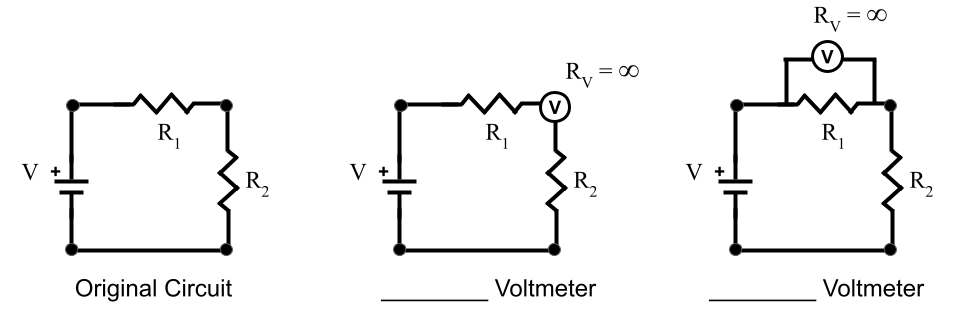
A circuit with two resistors is shown below. We want to use a voltmeter to measure the voltage drop of resistor \(R_1\). The circle with a V represents the voltmeter device, which measures the voltage difference across itself.
Explore
- Annotate the models with the following:
- Color code the wires to show different voltage values.
- Set up voltage equation(s) for the different paths and current equations for any junctions. Be sure to have equations for the resistor and voltmeter in each circuit (they might be in the same equation or need their own).
- Label the voltmeter “series” if it is in series with the resistor and “parallel” if it is in parallel with the resistor.
- According to the diagram, what is the resistance of a voltmeter?
Critical Thinking & Concept Invention
- Visually, which configuration looks like the voltage difference across the voltmeter matches a resistor in the circuit? Explain your thinking.
- Calculate the voltage difference and current through the resistor and voltmeter in each case. Use values:
\(V=12V,\; R_1=150\Omega,\; R_2=175\Omega\)
- Based on your calculations, should voltmeters be set up in series or parallel with resistors? Explain your reasoning.
- What might be problematic about setting up a voltmeter the wrong way?
1.3 Current Meters
Model
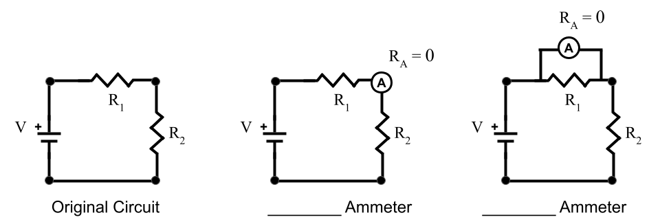
A circuit with two resistors is shown below. We want to use an ammeter to measure the current through resistor \(R_1\). The circle with an A represents the ammeter device, which measures the current going through itself.
Explore
- Annotate the models with the following:
- Color code the wires to show different voltage values.
- Set up voltage equation(s) for the different paths and current equations for any junctions. Be sure to have equations for the resistor and voltmeter in each circuit (they might be in the same equation or need their own).
- Label the ammeter “series” if it is in series with the resistor and “parallel” if it is in parallel with the resistor.
- According to the diagram, what is the resistance of an ammeter?
Critical Thinking & Concept Invention
- Visually, which configuration looks like the current through the ammeter matches the current through a resistor in the circuit? Explain your thinking.
- Calculate the voltage difference and current through the resistor and ammeter in each case. Use values:
\(V=12V,\; R_1=150\Omega,\; R_2=175\Omega\)
- Based on your calculations, should ammeters be set up in series or parallel with resistors? Explain your reasoning.
- What might be problematic about setting up an ammeter the wrong way?
Summary
The way we connect voltmeters and ammeters to a circuit can have an impact on the voltages and currents in the circuit. If connected incorrectly, the measurements will not reflect the same values in the circuit when those devices are not present and the circuit could become dangerous or destructive.
Voltmeters are connected in __________ with resistors because resistors in __________ have the same voltage drop. Voltmeters have a resistance of __________ so that they draw zero current.
Ammeters are connected in __________ with resistors because resistors in __________ have the same current. Ammeters have a resistance of __________ so that they do not result in a voltage drop.
Memorizing these patterns can be a helpful shortcut, but the important thing is that you can use the resistances of ideal voltmeters and ammeters to predict their effect and measured values in a circuit by treating them like resistors.
1.4 Brightness and Power
Model
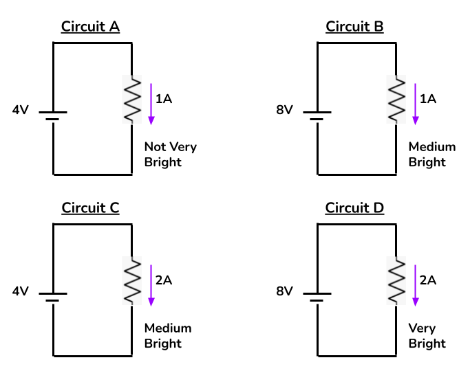
Explore
- Fill in the table to organize information about voltage, current, and light brightness.
| Circuit | Voltage Drop | Current | Brightness |
|---|---|---|---|
| A | |||
| B | |||
| C | |||
| D |
- Summarize how brightness seems to relate to voltage and current.
Critical Thinking & Concept Invention
- What we perceive as brightness is based on the power of the lightbulb. Identify the appropriate proportionalities based on the previous patterns.
\(P \propto I\) OR \(P \propto \frac{1}{I}\)
\(P \propto \Delta V\) OR \(P \propto \frac{1}{\Delta V}\)
- Use your two proportional relationships to suggest an equation for power. Then use Ohm’s Law to create two other versions of the equation: one without current and one without voltage.
\(P=\)
\(P=\)
\(P=\)
- As a group, derive the equation for power a different way:
- Use the relationship that \(P=\frac{dE}{dt}\) and that charges moving through a circuit satisfy \(dE=dU_{ele}\) to construct an equation for power below the energy equation.
- Group the differential quantities together. As a group, identify what this differential ratio represents and rewrite the equation below.
\(dU_{ele}=dQ\,\Delta V\)
\(P_{ele}=\)
\(P_{ele}=\)
Summary
Power represents how much energy flows into or out of a system every second. Power has units of Watts (W), which are Joules per second (J/s).
In lightbulbs and resistors, power is typically negative because energy leaves the circuit. The negative sign comes from the \(\Delta V\) part of the equation when using \(P=I\Delta V\). It is often easier to calculate the magnitude of power (absolute value) and interpret the direction energy flows based on the context of the problem.
This is necessary if you use either of the other equations for power since they involve squared quantities.
Apply
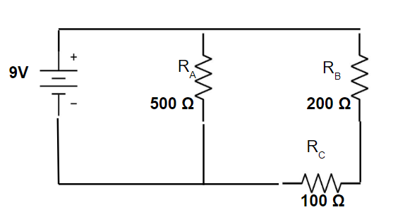
Determine the power in each resistor and the total power from the battery (sum of all powers). Discuss which version of the power equation you want to use.
This page titled 1.3: Circuit Devices and Measurements was last modified on Tue, 06 Oct 2026 03:05:23 GMT and is shared under a CC BY 4.0 license and was authored, remixed, and/or curated by Andrew Totah-McCarty.
The book could not be loaded just now.