Opening the book…
Let's start with the load. With the same \(25 \ \Omega\) resistor for the load, and plot its admittance . If we start moving away from the load towards the generator, in about we again run into the circle which represents . This is such an important circle is has gained its own name, and it is frequently called the matching circle shown in Figure \(\PageIndex{1}\).
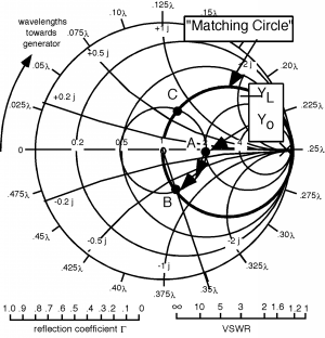
Figure \(\PageIndex{1}\): Getting to the Matching Circle
Note that to find out how far we had to move, we had to start at relative position as our zero, or reference location. Point \(B\) seems to be at about on the scale, and since we started at , the distance is . At point \(B\), . Thus, if we add a susceptance with a value of \(i 0.014 \ \Omega^{-1}\), we would again match the line. Positive susceptance comes from a capacitor as well, and so Figure \(\PageIndex{2}\) shows how we match.
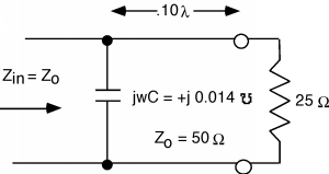
Figure \(\PageIndex{2}\): Matching with a shunt capacitor
Note that we are not required to go to point \(B\). Any point on the matching circle that we can get to is fair game. Another such point is \(C\) in Figure \(\PageIndex{1}\). This is at a distance of about from the load. At \(C\), and so we would put in an inductor, with a susceptance as in Figure \(\PageIndex{3}\).
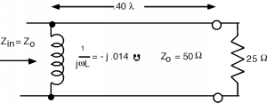
Figure \(\PageIndex{3}\): Matching with a shunt inductor
This page titled 6.14: Introduction to Parallel Matching was last modified on Tue, 25 Aug 2026 20:54:11 GMT and is shared under a CC BY 1.0 license and was authored, remixed, and/or curated by Bill Wilson via source content that was edited to the style and standards of the LibreTexts platform.
The book could not be loaded just now.