Opening the book…
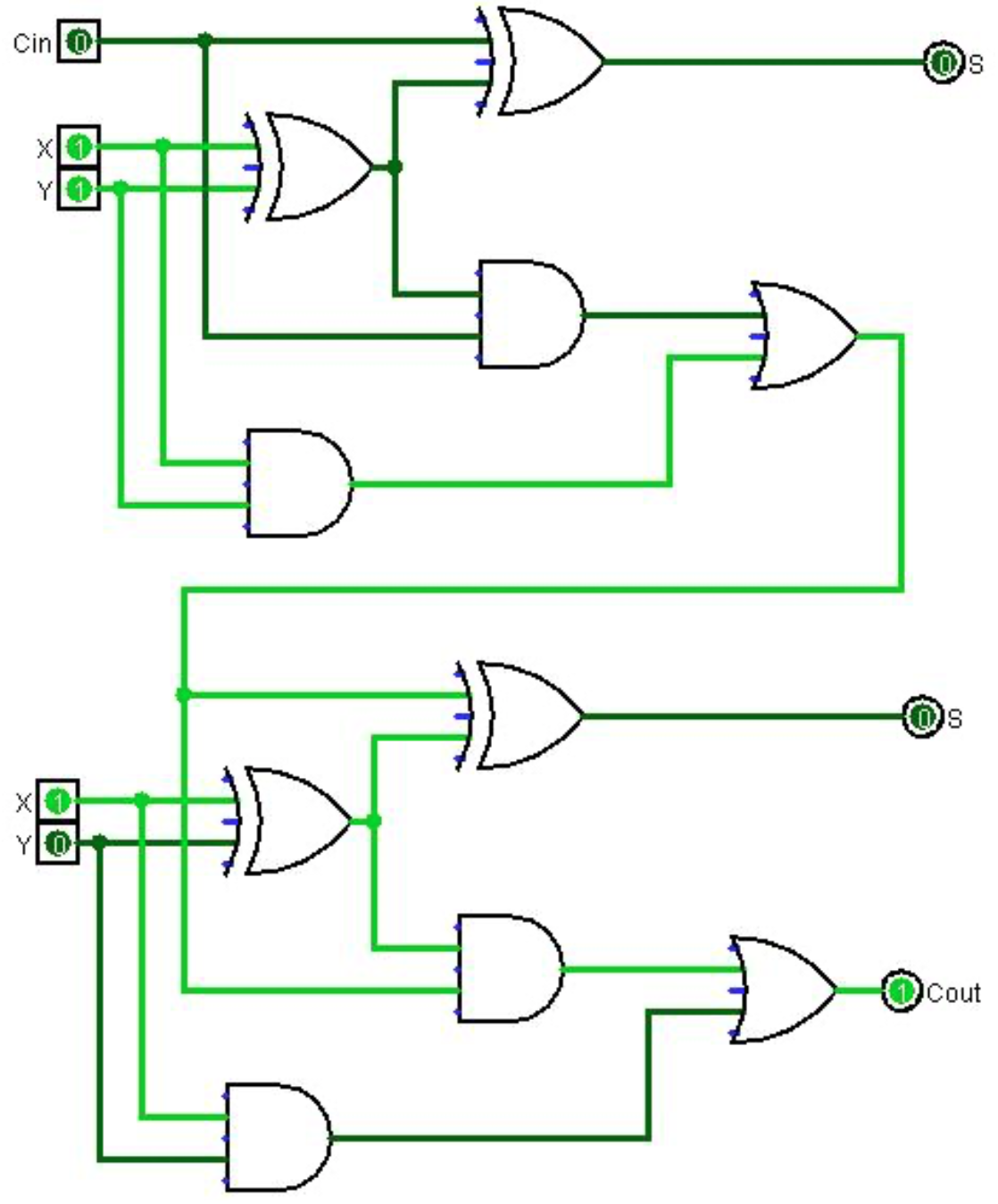
The full adder forms the basis for all arithmetic in a CPU. To illustrate this, a 2-bit adder is represented in Logisim in the Figure \(\PageIndex{1}\). This adder is implemented by using two instances of the 1-bit adder, and connecting the Cout from the first adder to the Cin of the second adder The adder shown below is adding X=112 (310) plus Y = 012 (110), resulting in 1002 (410), as expected. To create a n-bit adder (for example, a 32 bit adder used in many modern CPUs), 32 full adders can be wired together in a series, with the Cout of each bit being connected to the Cin of the next bit.
This page titled 6.4: 2-Bit Adder Circuit was last modified on Thu, 27 May 2021 01:12:27 GMT and is shared under a CC BY 4.0 license and was authored, remixed, and/or curated by Charles W. Kann (The Cupola: Scholarship at Gettysburg College) via source content that was edited to the style and standards of the LibreTexts platform.
The book could not be loaded just now.