Opening the book…
When a beam or frame is subjected to transverse loadings, the three possible internal forces that are developed are the normal or axial force, the shearing force, and the bending moment, as shown in section k of the cantilever of Figure 4.1. To predict the behavior of structures, the magnitudes of these forces must be known. In this chapter, the student will learn how to determine the magnitude of the shearing force and bending moment at any section of a beam or frame and how to present the computed values in a graphical form, which is referred to as the “shearing force” and the “bending moment diagrams.” Bending moment and shearing force diagrams aid immeasurably during design, as they show the maximum bending moments and shearing forces needed for sizing structural members.
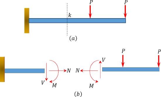
\(Fig. 4.1\). Internal forces in a beam.
This page titled 4.1: Introduction was last modified on Thu, 15 Apr 2021 18:30:24 GMT and is shared under a CC BY-NC-SA 4.0 license and was authored, remixed, and/or curated by René Alderliesten (TU Delft Open) via source content that was edited to the style and standards of the LibreTexts platform.
The book could not be loaded just now.